- Forum posts: 1
Mar 14, 2018, 7:54:27 AM via Website
Mar 14, 2018 7:54:27 AM via Website
I am designing an interface for my car steering wheel to a Android head unit, using a Sparkfun Arduino Pro Micro to handle the USB side of things. The steering wheel buttons use three wires and a [resistor][1] ladder for the buttons, as shown in this diagram from the service manual:
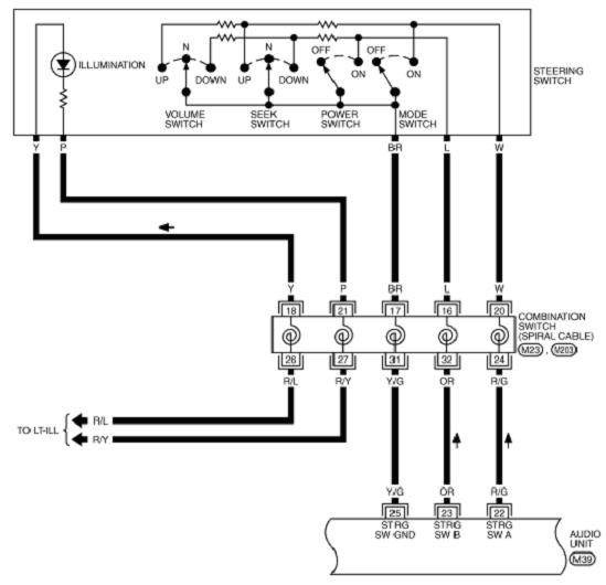
Each resistor in the diagram is the same value. My current solution is looks like this:
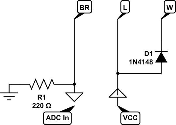
Which works on my PC, but causes two problems in the car
- Pressing "Power Switch" or "Mode Switch" causes a brown-out on the
micro controller and resets it, most likely due to exceeding the USB
current. - The car is a much noisier environment and the "Volume Switch"
buttons are not distinguishable reliably in the car, no matter how
much smoothing i do in code.
Ideally what I need is to know which line (L or W) is being pressed when the ADC reads a value. This would make the noise far less of an issue and I could then probably apply some sort of current limiting to eliminate the brown-outs without worrying about compressing the ADC range of values too much (and lose the diode).
Is there a simple way I can read the value at the ADC and use a digital pin to figure out which line was pressed (hopefully without too many components)?